


A 4-20mA loop only carries one number. HART was built to change that without touching the wiring.
Highway Addressable Remote Transducer — HART — puts a digital signal on top of the same two wires already carrying the analog process variable. The loop keeps working exactly as it did before; the digital layer rides alongside it. That’s the whole premise, and it’s why HART instruments from the 1980s still show up on new P&ID drawings today.
Quick facts
| Item | Value |
|---|---|
| Protocol name | HART (Highway Addressable Remote Transducer) |
| Signal type | Digital signal superimposed on a 4-20mA analog current loop |
| Physical layer | Bell 202 FSK — 1200 Hz = logic 1, 2200 Hz = logic 0 |
| Bit rate | 1200 bps |
| Typical update rate | 2-3 messages per second |
| Wiring modes | Point-to-point (device address 0) or multidrop (up to 64 devices, address 0-63) |
| Current revision in common use | HART 7 |
| Typical applications | Temperature, pressure, flow, level, valve position |
How the digital signal actually gets on the wire
HART uses frequency-shift keying (FSK) based on the Bell 202 standard. A logic 1 is represented by a 1200 Hz sine wave, a logic 0 by 2200 Hz. Both frequencies average to zero over a full cycle, so the digital signal doesn’t add any net DC offset to the loop current — the 4-20mA reading your control system sees is unaffected by the communication happening on top of it.
The tradeoff is speed. HART is not a fast protocol. Digital updates typically arrive two to three times per second, which is fine for configuration, diagnostics, and secondary variables, but not a substitute for the analog signal when you need control-loop response time.

Two wiring topologies, two very different use cases
HART supports two distinct connection modes, and the difference matters when you’re planning a loop.
Point-to-point (4-20mA compatible mode). This is the default. The loop current continues to represent the primary variable, and the digital signal rides on top for configuration, diagnostics, and secondary variables. In this mode the device’s polling address is fixed at 0. A handheld communicator or an AI card with a HART-capable input can talk to the device without disturbing the 4-20mA signal going to the control system.

Multidrop (networking mode). Here the loop current is fixed at a constant 4mA — it no longer represents a process value — and every device on the segment communicates purely digitally by address. This lets you put multiple transmitters on one pair of wires when you don’t need the analog signal, which is useful for monitoring points that don’t feed a control loop. HART supports up to 64 devices in short-address networking, addressed 0 to 63.

One practical detail that trips people up: HART communication needs loop resistance in a specific window to work reliably, separate from whatever resistance the loop needs for the 4-20mA signal itself. As a rough reference point, HART-capable modules typically specify something in the 230Ω to 1100Ω range for the communication path (exact figures vary by device — check the datasheet), on top of a wider allowable range for the analog current alone. If your loop resistance falls outside the HART-capable window, the analog signal can still work while the digital communication fails intermittently or not at all.
HART 5, 6, and 7 — what actually changed
The protocol has gone through three major revisions still in common use:
- HART 5 — the long-standing baseline. Single burst message, address range 0-15 in multidrop mode.
- HART 6 — added flexible/multiple secondary variable structures and improved batching of commands.
- HART 7 — extended addressing to 0-63, added multiple burst messages, event notification, and defined WirelessHART as part of the same command set. This is the version most new instruments ship with today.
Burst mode is worth calling out separately because it’s an optional feature, not a given. In burst mode, the device pushes data out on a schedule instead of waiting to be polled, which is useful when a host needs faster or more predictable updates than standard request-response polling delivers. Not every HART device supports it — it’s something to confirm on the datasheet rather than assume.
The command structure, briefly

HART commands fall into three groups. Universal commands work on every HART device regardless of manufacturer — read the primary variable, read tag/descriptor, that kind of thing. Common-practice commands are widely implemented but optional — things like write damping value or self-test. Device-specific commands expose whatever is unique to that instrument. When you’re integrating a HART device into a host system, the universal command set is what guarantees basic interoperability; anything beyond that depends on whether the host has a matching device description (DD) file.
Why HART Is Still Widely Used
Given how much faster fully digital buses run, it’s a fair question why HART — a 1200 bps protocol from the 1980s — is still specified on new projects. A few reasons keep coming up:
- Backward compatible with 4-20mA. The analog signal an existing control system already reads doesn’t change. Nothing on the I/O card or the control strategy needs to be touched to add HART.
- Retrofit without rewiring. Adding digital diagnostics and configuration to an existing analog loop is a matter of connecting a handheld communicator or a HART-capable multiplexer — not pulling new cable.
- Configuration and diagnostics without interrupting the process. Because the digital layer doesn’t disturb the analog value, a technician can read diagnostic status or adjust damping and range on a live loop without taking the measurement offline.
- Installed base. Decades of HART instruments are already in service across refineries, chemical plants, and power generation. New instruments need to interoperate with that installed base more than they need to be the fastest protocol available.
Where HART Shows Up in a Plant
HART is used across most analog-loop instrument types, not just temperature measurement:
- Temperature transmitters
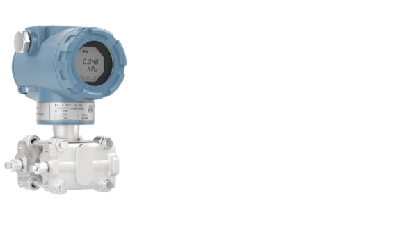
- Pressure transmitters
- Flow meters
- Level instruments
- Control valve positioners
- Gas analyzers
- Tank gauging systems
Any device that already outputs 4-20mA is a candidate for a HART variant, since the protocol was built to layer onto that existing signal rather than replace it.
HART vs Other Industrial Protocols
HART sits in a specific niche — hybrid analog/digital — that’s worth comparing against fully digital fieldbus options when you’re deciding what a new installation should use:
| Protocol | Signal | Typical Speed | Topology | Common Use |
|---|---|---|---|---|
| HART | 4-20mA analog + FSK digital overlay | 1200 bps | Point-to-point or multidrop (≤64 devices) | Retrofit, hybrid analog/digital plants |
| PROFIBUS PA | Fully digital, bus-powered | 31.25 kbps | Multidrop bus segment | Process plants, hazardous areas |
| FOUNDATION Fieldbus H1 | Fully digital, bus-powered | 31.25 kbps | Multidrop bus segment | Distributed control, function blocks |
| Modbus RTU | Fully digital, RS-485 | Up to 115.2 kbps (commonly 9600-19200 bps in practice) | Multidrop, master/slave | PLC/RTU integration, SCADA |
These are general protocol specifications, not tied to any one manufacturer’s implementation. Detailed comparisons — HART vs PROFIBUS, HART vs FOUNDATION Fieldbus — are worth their own articles; this table is meant to place HART on the map, not replace that deeper analysis.
What to check before you specify a HART device
A few questions worth answering before ordering, based on how the protocol actually behaves in the field:
- Which HART revision does the host support? A HART 7 device will still talk to a HART 5 host using the common command set, but multiple-burst-message and extended addressing features won’t be available.
- Point-to-point or multidrop? This decides whether you need the analog signal at all, and changes how you think about polling address and loop current behavior.
- Does the application need burst mode? If a host needs update rates faster than standard polling delivers, confirm burst mode is supported before specifying, not after installation.
- Loop-powered or externally powered? Loop-powered transmitters draw operating current from the same 4-20mA loop; externally powered devices need a separate supply. This affects both wiring and power budget on long loops with multiple devices.
- Is the installation in a hazardous area? If so, confirm the explosion-protection marking (e.g., Ex ia, Ex d) against the actual zone classification and ask for the current certificate — don’t rely on a datasheet line item alone. Certification details change between hardware revisions.
Examples of HART Devices
Implementations vary between manufacturers, and even between product lines from the same vendor — supply voltage windows, channel count, and burst mode support all differ by model. A few examples from Microcyber’s current catalog show how the concepts above show up in an actual datasheet.
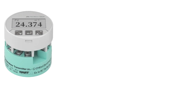
Microcyber’s NCS-TT106H is a single-channel, HART 7 Temperature Transmitter built around this exact point-to-point model: 4-20mA output with HART riding on top, non-intrinsically-safe supply range of 12-42VDC or 12-30VDC in the IS variant, and Ex ia IIC T4 Ga protection for hazardous-area installs. It accepts RTD, thermocouple, resistance, and millivolt inputs on a single input channel.
For applications that need faster or richer digital updates, the NCS-TT306HH is the dual-channel version with HART 7 burst mode support, a wider supply range for both non-IS (10-45VDC) and IS (10-30VDC) configurations, and an optional -55°C to 85°C operating range for cold environments. Burst mode here means the host can be configured to receive scheduled updates rather than relying purely on polling.
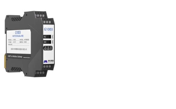
Not every field device speaks HART natively. For integrating a Modbus RTU slave device into a HART-based system, Microcyber’s M0310 module acts as a protocol converter — Modbus RTU in, 4-20mA + HART 7 out — with a HART-communication load resistance window of 230-1100Ω, matching the practical constraint described above. The MC0310 does the same conversion in a smaller PCB-mount form factor.
For bench work rather than installed loops, the NCS-HM105 is a HART modem/interface (USB or RS232) used with configuration software during calibration or commissioning, rather than a field-mounted transmitter.
Where this fits in a real project
None of this replaces reading the specific datasheet for the device you’re specifying — supply voltage windows, load resistance limits, and certification markings vary by model and by hardware revision, and the numbers above are the current published specifications for the models named. If you’re speccing a HART loop for a hazardous area, get the current explosion-protection certificate directly rather than relying on a datasheet line, since certification status can change between revisions.
The next article in this series looks at PROFIBUS DP versus PA, a useful comparison if you’re deciding between a 4-20mA/HART loop and a full digital bus for a new installation.
FAQ
Is HART analog or digital?
Both. The 4-20mA analog current still carries the primary variable in point-to-point mode; a digital FSK signal rides on top of it for configuration, diagnostics, and secondary variables.
Can HART work without 4-20mA?
Yes. In multidrop mode the loop current is fixed at 4mA and carries no process value — communication is purely digital, addressed by device.
How many devices can be on a HART multidrop network?
Up to 64 devices in HART 7 short-address networking, using addresses 0 through 63.
Is HART 7 backward compatible with HART 5?
HART 7 devices still respond to the universal and common-practice commands that a HART 5 host recognizes. Features specific to HART 7 — multiple burst messages, extended addressing up to 63 — require a host that supports HART 7.
Does HART require special cable?
The protocol itself doesn’t mandate a specific cable type, but the loop needs to fall within the resistance window a given device specifies for HART communication (commonly in the low hundreds of ohms), separate from whatever resistance the loop needs for the 4-20mA signal alone. Check the specific device’s datasheet.
Can a PLC read HART data?
Yes, if the PLC has a HART-capable analog input card, or is paired with a HART multiplexer or gateway. A plain 4-20mA-only input card reads just the analog signal and ignores the digital layer.
Can HART and 4-20mA run at the same time?
Yes — that’s what point-to-point mode is. The digital signal doesn’t add any net DC offset, so the 4-20mA value the control system sees is unaffected by the HART communication happening alongside it.