
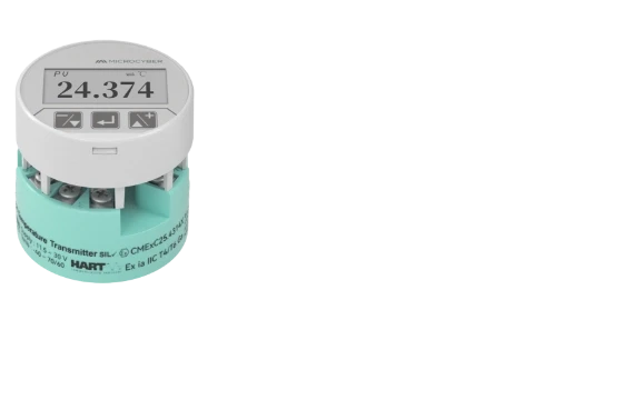
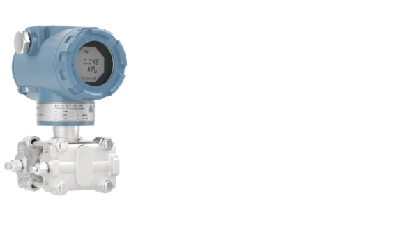
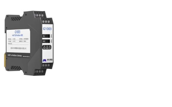
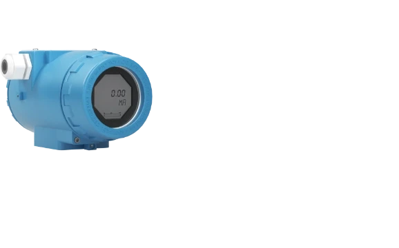


The HT5700 HART modem IC is a low-power, single-chip HART communication solution for HART FSK half-duplex communication. It integrates FSK modulation and demodulation, receive filtering, signal detection, signal generation, an internal reference, and clocking functions in one device.
Designed for HART circuits, the HT5700 complies with HART physical layer requirements and provides a UART interface for communication with a host controller. It operates from a 2.7 V to 5.5 V supply and supports multiple clocking configurations, including an external crystal, external CMOS clock source, and internal RC oscillator.
HART Modem for 4–20 mA HART Communication
HART communication transmits digital information over analog 4–20 mA current signals using FSK modulation. The HT5700 is designed as a single-chip, low-power HART FSK half-duplex modem and supports the HART physical layer.
The HT5700 transmits and receives 1.2 kHz and 2.2 kHz carrier signals. The device uses a standard UART interface with TXD, RXD, RTS, and CD signals for communication control and data transfer.

HART FSK Modem with Integrated Functions
The HT5700 integrates functions required for HART communication, including:
- FSK modulation and demodulation
- Integrated receive band-pass filter
- Carrier detection
- Internal voltage reference
- Buffered HART output
- Internal precision RC oscillator
- External crystal clock support
- External CMOS clock input
- UART interface
- Power-down mode
- Full-duplex operation
The integrated receive filter can be used internally or bypassed when an external filter configuration is required. The device also provides an internally buffered HART output.
HART Modem IC Applications
The HT5700 is specified for several HART communication applications, including:
- Field transmitters
- HART multiplexers
- PLC analog I/O modules
- DCS analog I/O modules
- HART network connectivity
These applications are listed in the HT5700 user manual.
HART Modem with UART Interface
The HT5700 uses a standard UART interface for digital communication between the modem and the host controller.
The main digital interface signals include:
| Pin | Function |
|---|---|
| TXD | Transmit data input to the modulator |
| RXD | Receive data output from the demodulator |
| RTS | Request to send and transmit/receive mode control |
| CD | Carrier detect output |
| RESET | Active-low reset and power-down control |
| DUPLEX | Full-duplex operation control |
TXD provides data to the FSK modulator, while RXD provides demodulated data from the HART receiver. RTS controls the transmit and receive functions, and CD indicates that a valid carrier has been detected.
HART FSK Modulator
The HT5700 FSK modulator converts UART-encoded HART data at the TXD input into a sequence of 1200 Hz and 2200 Hz tones.
The generated signal is internally buffered and provided at the HART_OUT pin. The modulator is enabled by bringing RTS low.
The modulator uses a DDS engine to generate the 1.2 kHz and 2.2 kHz sine-wave signals in digital form before digital-to-analog conversion. The design provides continuous phase signals when switching between the two frequencies.
HART FSK Demodulator
In receive mode, the HT5700 detects a valid carrier through the CD output and accepts the HART FSK signal at the HART_IN input.
The received signal is processed by the ADC, digital filtering, and digital demodulation functions before the recovered HART data is provided at the RXD UART output. The HART bit stream uses a standard UART frame consisting of a start bit, 8-bit data, one parity bit, and a stop bit.
Internal and External HART Filtering
The HT5700 provides two filter configuration options.
Internal Filter
With the internal filter enabled, the HART signal is applied to the HART_IN pin. This configuration integrates the receive band-pass filter into the device and can reduce the number of external filter components.
External Filter
An external band-pass filter can be connected through the ADC_IP input. This configuration allows the HART input signal to be processed through an external filter network. For safety-critical applications, the manual specifies isolation requirements between the HT5700 and the high voltage of the loop supply.
Low Power HART Modem
The HT5700 is designed for low-power HART communication applications.
The datasheet specifies a maximum supply current of 115 μA in receive mode as a feature. Current consumption varies according to operating mode, clock configuration, and reference configuration. The specification table provides separate values for the demodulator, modulator, crystal oscillator, internal oscillator, and power-down mode.
In power-down mode, the receive, transmit, and oscillator circuits are switched off. The typical current consumption is 30 μA under the conditions specified in the manual.
HART Modem Clock Configuration
The HT5700 supports three main clocking configurations:
- External crystal
- External CMOS clock
- Internal RC oscillator
The internal oscillator has a typical frequency of 1.2288 MHz and 0.5% precision. The device can also provide a buffered clock output through CLKOUT depending on the selected clock configuration.
The clock configuration is controlled through the XTAL_EN, CLK_CFG0, and CLK_CFG1 pins.
HART Modem Full-Duplex Operation
In addition to half-duplex operation, the HT5700 supports full-duplex operation.
When full-duplex mode is enabled, the modulator and demodulator operate at the same time. The manual describes this mode for self-test of the HART device and the signal path between the HART device and host controller. Full-duplex operation is enabled by setting the DUPLEX pin high.
HT5700 Electrical Specifications
| Parameter | Specification |
|---|---|
| HART communication | HART FSK |
| Modem type | Single-chip, half-duplex modem |
| Supply voltage | 2.7 V to 5.5 V |
| Digital interface supply | 1.71 V to 5.5 V |
| Operating temperature | −40°C to +125°C |
| HART mark frequency | 1200 Hz |
| HART space frequency | 2200 Hz |
| HART output | Buffered HART FSK signal |
| Interface | UART |
| Receive filter | Internal or external |
| Clock options | External crystal, CMOS clock, internal RC oscillator |
| Internal oscillator | 1.2288 MHz typical |
| ESD rating | 8 kV HBM |
| Package | 4 mm × 4 mm QFN |
The electrical specifications and package information are taken from the HT5700 user manual.
HT5700 HART Modem Pin Configuration
The HT5700 uses a 24-lead QFN package with dedicated pins for power, HART signal input and output, UART communication, clock configuration, filtering, reference control, and operating mode control.
Key pins include:
| Pin | Description |
|---|---|
| HART_IN | HART FSK signal input |
| HART_OUT | HART FSK signal output |
| ADC_IP | ADC input for external filter configuration |
| TXD | Transmit data input |
| RXD | UART receive data output |
| RTS | Request-to-send control |
| CD | Carrier detect output |
| XTAL1 | External crystal or clock input |
| XTAL2 | External crystal connection |
| CLKOUT | Buffered clock output |
| REF | Internal reference output or external reference input |
| REF_EN | Reference enable |
| FILTER_SEL | Internal/external band-pass filter selection |
HART Modem Circuit Design
The HT5700 supports different HART circuit configurations based on filtering, reference, and clock requirements.
The user manual provides typical connection diagrams for internal and external filter configurations, as well as application information covering supply decoupling and transient voltage protection.
For loop-powered applications, the manual also provides recommendations for supply decoupling and series resistance to reduce the effect of current-draw variations on the loop.
Why Use HT5700 for HART Communication?
The HT5700 combines HART FSK modem functions, filtering, signal detection, clock generation, reference functions, and UART connectivity in a single device.
Its documented features include:
- HART physical layer compliance
- 2.7 V to 5.5 V supply
- 1.71 V to 5.5 V digital interface supply
- 1200 Hz and 2200 Hz HART FSK carriers
- Internal or external receive filtering
- Internal precision RC oscillator
- External crystal and CMOS clock support
- UART interface
- Full-duplex operation
- 8 kV HBM ESD rating
- −40°C to +125°C operating temperature
These features make the HT5700 suitable for the HART communication applications specified in the product manual.
HT5700 HART Modem FAQ
What is the HT5700?
The HT5700 is a single-chip, low-power HART FSK modem designed for HART communication applications and compliant with HART physical layer requirements.
What type of HART modem is HT5700?
The HT5700 is a HART FSK half-duplex modem. It supports transmission and reception using 1200 Hz and 2200 Hz carrier signals.
Does the HT5700 support a UART interface?
Yes. The HT5700 provides a UART interface through TXD, RXD, RTS, and CD signals.
Does the HT5700 have an internal HART filter?
Yes. The HT5700 includes an integrated receive band-pass filter. It can also be configured to use an external filter through ADC_IP.
What supply voltage does the HT5700 require?
The specified VCC range is 2.7 V to 5.5 V, while the digital interface supply IOVCC supports 1.71 V to 5.5 V.
What applications does the HT5700 support?
The manual lists field transmitters, HART multiplexers, PLC and DCS analog I/O modules, and HART network connectivity as applications.
HT5700 User Manual
For detailed pin information, electrical specifications, timing characteristics, clock configuration, HART filtering, typical circuits, and application information, refer to the HT5700 Low Power HART Modem User Manual.
HT5700 HART Modem IC
Microcyber’s HT5700 provides an integrated HART FSK modem solution with UART connectivity, internal filtering, multiple clock configurations, and support for HART physical layer requirements.
For technical information about the HT5700 HART modem IC, please contact Microcyber.


