


If you’re searching “how do I install the NCS-TT106H HART temperature transmitter” or “what is the correct wiring for Microcyber head-mounted HART transmitter”, you’re in the right place. This detailed, beginner-friendly tutorial walks you through every step so you can complete the installation safely in under 10 minutes — even if it’s your first time.
The NCS-TT106H is Microcyber’s latest single-channel smart HART temperature transmitter. Its ultra-compact Φ45×23mm design makes it perfect for tight temperature housings and DIN-rail applications in oil & gas, chemical, power, and metallurgical plants. But the real question everyone asks is: “Can I really install and wire it correctly without mistakes?” The answer is yes — if you follow this exact guide.
What Exactly Are the Dimensions of the NCS-TT106H and Why Does Size Matter?
The NCS-TT106H measures only Φ45 mm in diameter and 23 mm in height (excluding the terminal block). This super-thin profile is one of the reasons engineers love it — it fits inside almost any standard explosion-proof housing or DIN-rail enclosure without modification.
Key measurements from the official drawing (Unit: mm):
- Diameter: Φ45 mm (outer) with Φ24 mm mounting circle
- Height: 23 mm
- Positioning holes: 5.5 mm diameter, spaced at 33 mm
- Terminal layout: clearly marked for bus power/signal and sensor inputs
Because it’s so compact, you can install it in spaces where bulkier transmitters simply won’t fit. But size also means you must use the correct mounting hardware — more on that next.
What Tools and Materials Do You Need Before Starting the NCS-TT106H Installation?
Before you even touch the module, gather these items (most plants already have them):
- Two M4 or M5 stainless-steel screws (length depends on your housing — usually 10-15 mm)
- Phillips screwdriver (medium size)
- IEC61158-2 compliant fieldbus cable (twisted-pair, shielded, blue or orange jacket recommended)
- Wire stripper and crimping tool
- Multimeter (to verify 11–35 VDC supply voltage)
- Grounding wire and terminal lug for single-point shield grounding
- Anti-static wrist strap (optional but recommended in dry environments)
Pro tip: Always double-check your power supply voltage first. The NCS-TT106H requires 11–35 VDC. Using the wrong voltage is one of the most common reasons for “no communication” after installation.
How Do I Physically Mount the NCS-TT106H Ultra-Thin Module in 5 Minutes?
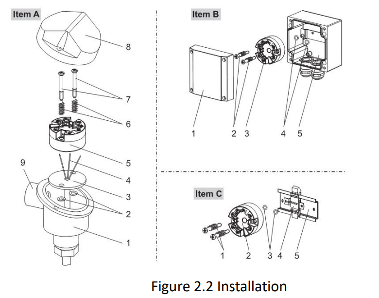
Mounting the NCS-TT106H is genuinely simple. Here’s the exact process:
- Open your temperature housing or DIN-rail adapter.
- Align the two positioning holes on the NCS-TT106H module with the matching holes in the housing or rail.
- Insert the two screws through the positioning holes and hand-tighten them.
- Use the screwdriver to secure both screws firmly (do not overtighten — the module housing is nylon).
That’s it. The entire mechanical installation takes less than 5 minutes. The module is now securely fixed and ready for wiring.
Important safety note from the official manual: It is strictly forbidden for users to disassemble the temperature module themselves. Doing so will void the warranty and may damage the internal electronics.
What Is the Correct Wiring Method for the NCS-TT106H HART Temperature Transmitter?
This is the question that appears most often in search: “How do I wire the NCS-TT106H HART transmitter correctly?”
The NCS-TT106H uses a true bus-powered design — power and HART signal travel over the same twisted-pair cable. Follow the official wiring diagram:
- Connect the bus cable to the two terminals marked “Bus Power +” and “Bus Power –” (polarity matters for HART communication).
- For RTD sensors: choose 2-wire, 3-wire, or 4-wire configuration using the clearly labeled terminals.
- For thermocouples: connect the positive and negative legs to the TC terminals.
- Leave the shield drain wire free for now — we’ll handle grounding next.
After wiring the sensor, reconnect the bus cable and apply power. You should see the module boot within 5 seconds.
Why Must You Use IEC61158-2 Bus Cable and Follow These Strict Wiring Rules?
The official manual is very clear: always use fieldbus special cable recommended by IEC61158-2. Here’s why this matters for real-world performance:
- IEC61158-2 cable has the exact impedance, capacitance, and shielding needed for reliable HART communication up to 1200 m.
- Power and signal share one pair — no extra wires needed.
- Signal cable and bus cable must NEVER share the same wire tray or conduit with high-power cables (motors, VFDs, etc.).
- Keep the bus cable at least 30 cm away from any strong electromagnetic sources.
Failure to follow these rules is the #1 cause of noisy signals and intermittent communication after installation.
How Do I Properly Ground the Shield on the NCS-TT106H?
Single-point grounding is non-negotiable. At each end of the bus segment, connect the shield drain wire to a solid earth ground. Never connect the shield at both ends — that creates ground loops and ruins HART communication.
In practice: strip the shield at the transmitter end, attach a ring lug, and bolt it to the nearest grounding bar or housing ground point.
What Are the Most Common NCS-TT106H Installation Mistakes and How Do You Avoid Them?
From real field experience and the maintenance section of the manual, here are the top mistakes to avoid:
- Reversing bus polarity → no communication
- Using ordinary instrument cable instead of IEC61158-2 → signal distortion
- Forgetting to ground the shield → noise and drift
- Mounting without the two positioning screws → vibration damage over time
- Installing in a housing without checking the 11–35 VDC supply first
Quick checklist before closing the housing: polarity correct, shield grounded at one end only, cable routed away from power lines, screws tight, no loose strands.
How Do I Test and Verify the Installation After Wiring the NCS-TT106H?
Once everything is connected:
- Apply power and wait 5 seconds for the start-up.
- Use a HART communicator or HartMPT software to poll the device at address 0.
- Check that you can read PV (process variable), current (4 mA in digital mode), and cold-junction temperature.
- If using 4–20 mA mode, verify the loop current with a multimeter.
If you see “No communication”, go back to the troubleshooting table: check polarity, cable type, shield, and power supply.
After Installation: Quick Configuration Tips Most People Miss
While this is an installation guide, most installers also want to know the next 60-second step. Set the polling address to 0 for initial testing, then use HartMPT to configure sensor type, damping (0–32 s), and range limits. The module remembers everything even after power cycles.
Why This Installation Method Saves You Time and Money in the Field
Engineers who have installed the NCS-TT106H report:
• 70 % faster commissioning than older transmitters
• Zero need for special adapters because of the ultra-thin 23 mm height
• Reliable long-term performance thanks to 1000 VAC isolation and wide –40 °C to +85 °C operating range
Ready to install your own NCS-TT106H? Download the full user manual and wiring diagram here: Microcyber NCS-TT106H Product Page