


If you’re developing a smart temperature transmitter, pressure transmitter, or other industrial field device and running into trouble with Microcyber’s MC series embedded core modules (such as MC0313 for FF, MC0307 for PA, or MC0310 for HART), you’re not alone. These compact 35mm × 35mm modules are designed for easy protocol switching, but power, interface, and configuration issues frequently slow down projects.
Here are the most common problems engineers face during integration — along with straightforward ways to solve them.

1. Power Supply Problems: Why the Module or Sensor Won’t Start Reliably
Many projects fail at the first power-up because the module can’t deliver enough current to the sensor or the loop.
Typical specifications to watch:
- MC0313 and MC0307 (FF/PA modules): Provide 3.3V and 6V outputs. When powered by 6V alone, the maximum available current is about 6mA.
- MC0310 (HART module): Roughly 3.4mA at 12V supply and up to 7mA at 24V. The HART core only supports 3.3V powering in standard versions — 5V needs customization.
Quick fixes:
- In two-wire (loop-powered) designs, prefer 24V to give more current margin.
- For four-wire setups, use a dedicated stable 6V supply for the module and keep total load current safely under 6mA.
- Always measure the actual current draw with a multimeter during early testing.
Done right, the modules run stably from -40°C to 85°C in most process industry environments.
2. Interface Issues: Why Modbus Communication Keeps Failing
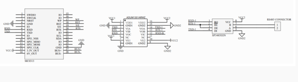
A frequent mistake is expecting a ready-to-use RS485 port. The MC series actually outputs TTL-level Modbus RTU (master mode), not RS485.
Important clarification:
- RS485 is the physical layer best suited for long-distance runs (up to 1200 meters) and multi-device networks.
- To get RS485, add a standard transceiver chip (like MAX485) on your carrier board for TTL-to-RS485 conversion.
All MC modules use the same 2.0mm pitch single-row 14-pin connector, so you can swap between HART, FF, or PA cores without changing your board layout — making protocol upgrades simple.
3. Configuration Problems: Why the Module Doesn’t Respond After Power-Up
Even with correct wiring, the module often stays silent until function blocks, addresses, damping, and alarm settings are properly configured.
Practical steps:
- Use the dedicated configuration tool that comes with the modules — it’s designed to be straightforward.
- For the FF module (MC0313), follow the recommended workflow with the FF tool kit; this usually cuts debugging time dramatically.
- Key parameters to set correctly: startup time (≤5 seconds), update rate (0.2s), damping (0–32 seconds), and alarm currents (21.75mA/3.7mA or similar).
Taking time to configure properly prevents most cases of “no communication” or “module not detected.”
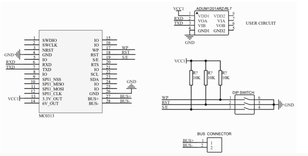
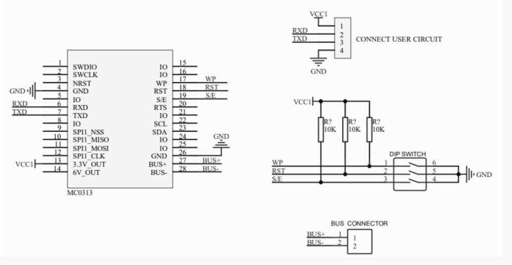
Recommended Circuits That Actually Work
Use these proven approaches to avoid basic wiring mistakes:
- Two-wire circuit: Combines bus power and 4-20mA + protocol signal on the same pair — simple and widely used.
- Four-wire circuit: Keeps power separate from the signal for better accuracy (0.03% FS) and lower temperature drift (50 ppm/°C).
- Four-wire with RS485: Adds the TTL-to-RS485 conversion for reliable long-distance Modbus links to PLCs or DCS.
These circuits have been used successfully in many transmitter projects and help meet typical industrial EMC requirements.
Other Useful Tips
- Reserve pins 1, 2, 5, and 8 on the connector — they are reserved for firmware upgrades and should not be used in normal operation to keep compatibility across protocols.
- Compared to the older M series, MC modules are smaller and support both two-wire and four-wire devices, but without built-in Modbus isolation. Migration is usually possible with a few extra components.
- If your application needs extra features (e.g., custom calibration for gas detectors, special alarm logic, or synchronization with the device LCD), software customization is often the easiest path.
Moving Forward
The MC series “same size, same interface, easy upgrade” design really does simplify multi-protocol development — once you get past the initial power, interface, and configuration hurdles.
If your MC core module isn’t behaving as expected, start by double-checking power budget and TTL/RS485 conversion, then verify configuration. These small details solve the majority of integration headaches.