




Product Overview
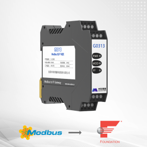
MC0313 is a compact embedded core module that converts Modbus RTU slave devices into FOUNDATION Fieldbus H1 devices. It is designed for OEM manufacturers who want to add FOUNDATION Fieldbus communication capability to their existing Modbus instruments with minimal hardware changes.
As a Modbus master, the module communicates with Modbus RTU slave devices through its TTL serial interface and maps Modbus data to FOUNDATION Fieldbus device variables and function blocks.
The MC0313 is part of Microcyber’s MC series of embedded core modules, featuring a compact 35 × 35 mm form factor and a 2.0 mm pitch 14-pin connector. By embedding the MC0313 into equipment with Modbus RTU communication capabilities, the user equipment can be converted into a FOUNDATION Fieldbus H1 device without developing a protocol stack from scratch.
Key Features
- Modbus RTU to FOUNDATION Fieldbus conversion – Enables Modbus RTU devices to communicate with FF H1 networks
- Compact 35 × 35 mm core module – Small footprint for space-constrained OEM designs
- 2.0 mm pitch 14-pin interface – Compatible with all Microcyber MC series modules
- Modbus master operation – Actively polls the connected Modbus slave device
- Supports 1 Modbus slave device – Dedicated connection for single-device integration
- 32 I/O channels – 8 AI, 8 AO, 8 DI, and 8 DO channels
- Rich function block set – Includes 6 AI, 2 AO, 4 DI, 4 DO, 2 PID, and 1 Modbus Transducer Block
- Flexible Modbus configuration – Configurable register address, data format, and function code
- Easy protocol upgrade – Replace MC series modules to implement different protocols
- OEM-ready – Users retain independent intellectual property rights for their products
Modbus RTU to FOUNDATION Fieldbus Integration
The MC0313 enables Modbus RTU slave devices to be integrated into FOUNDATION Fieldbus systems without redesigning the complete field device communication architecture.
The module operates as a Modbus master and retrieves data from a Modbus RTU slave device through the TTL serial interface. The acquired data is mapped into the module’s Modbus Transducer Block and transferred through FOUNDATION Fieldbus function blocks such as AI, AO, DI, and DO.
As a FOUNDATION Fieldbus device, the module communicates with Modbus devices through simple configuration and transfers data to the control system via the FF bus.

How the MC0313 Works
The MC0313 works as a communication bridge between a Modbus RTU slave device and a FOUNDATION Fieldbus network.
Modbus RTU Device → MC0313 TTL Interface → Modbus Transducer Block → FF Function Blocks → FOUNDATION Fieldbus Control System
The module reads Modbus register data and maps the data into transducer block parameters. The mapped process data can then be transferred to AI, AO, DI, and DO function blocks for communication with the FOUNDATION Fieldbus control system.
The module supports 1 Modbus slave device and provides 8 groups of analog input/output and discrete input/output parameters, totaling 32 channels. It configures Modbus device data into transducer block parameters via Modbus registers and provides data support for the FF system via channels between variables and AI, AO, DI, and DO function blocks.
Applications
- Integrating Modbus RTU transmitters into FOUNDATION Fieldbus networks
- Upgrading existing Modbus instruments to FF H1 communication
- OEM field device development with FOUNDATION Fieldbus support
- Space-constrained embedded designs requiring FF communication
- Retrofit projects where instruments need FF communication without full redesign
Technical Specifications
| Parameter | Specification |
|---|---|
| Supported Modbus Device | Modbus RTU slave device |
| FF Bus Power | 9–32 VDC |
| Quiescent Current | ≤14 mA |
| Bus Protocol | Two-wire FOUNDATION Fieldbus H1 |
| Isolation Voltage | Modbus and FF buses are not isolated |
| Operating Temperature | -40°C to +85°C |
| Operating Humidity | 5–95% RH |
| Start-up Time | ≤5 s |
| Weight | 16 g |
| Module Size | 35 × 35 mm |
| Interface | TTL level |
Supported Modbus Function Codes
The MC0313 supports the following Modbus function codes:
| Function Code | Description |
|---|---|
| 01 | Read coil status |
| 02 | Read discrete input status |
| 03 | Read holding registers |
| 04 | Read input registers |
| 05 | Write single coil |
| 06 | Write single register |
| 15 | Write multiple coils |
| 16 | Write multiple registers |
FOUNDATION Fieldbus Function Blocks
The default configuration includes the following function blocks:
| Function Block | Description |
|---|---|
| Resource Block (RES) | Device identification in the field |
| Modbus Transducer Block (MTB) | Configures Modbus communication parameters |
| Analog Input (AI) × 6 | Transducer block input data with range conversion |
| Analog Output (AO) × 2 | Transfers output data to transducer block |
| Discrete Input (DI) × 4 | Achieves transducer block input data |
| Discrete Output (DO) × 4 | Transfers discrete output data to transducer block |
| PID Block × 2 | PID control with setpoint adjustment and PV filtering |
AI, AO, DI, and DO support up to 8 channels each, corresponding to analog/discrete input and output parameters of the Modbus Transducer Block.
Hardware Interface
The MC0313 uses a 2.0 mm pitch 14-pin connector to connect to the user board.
Pin definition:
| Pin | Name | Description |
|---|---|---|
| 1 | SWDIO | Data input/output (download interface) |
| 2 | SWCLK | Clock signal (download interface) |
| 3 | NRST | MCU reset signal (download interface) |
| 4 | GND | Reference ground |
| 5 | IO | Reserved GPIO |
| 6 | RXD | UART1 input, TTL level |
| 7 | TXD | UART1 output, TTL level |
| 8 | IO | Reserved GPIO |
| 9 | SPI1_NSS | Reserved SPI interface / GPIO |
| 10 | SPI1_MISO | Reserved SPI interface / GPIO |
| 11 | SPI1_MOSI | Reserved SPI interface / GPIO |
| 12 | SPI1_CLK | Reserved SPI interface / GPIO |
| 13 | 3.3V_OUT | Power output |
| 14 | 6.2V_OUT | Power output |
Additional pins (J1/J2 connectors):
| Pin | Name | Description |
|---|---|---|
| 17 | WP | Write protection DIP switch |
| 18 | RST | Reset DIP switch — restore to factory defaults |
| 19 | S/E | Simulation DIP switch (FF only) |
| 20 | RTS | UART1 RTS control for 485 communication |
| 24 | IO | Modbus communication status indicator (low active) |
| 25 | IO | FF communication status indicator (low active) |
| 26 | GND | Reference ground |
| 27 | BUS+ | Bus power supply positive |
| 28 | BUS- | Bus power supply negative |
Recommended Circuits
The MC0313 supports both 2-wire and 4-wire device connections. Refer to the user manual for detailed circuit diagrams:
- 4-wire device: Power and signal on the other side of the optocoupler need to be provided by the customer’s instrument board
- 2-wire device: VCC1 and GND1 are the module output power supplies, which can provide power to the customer’s instrument board
- 4-wire RS485 connection: VCC2 and GND2 are powered by the instrument
Modbus Configuration
The MC0313 is configured through the Modbus General Configuration Tool provided by Microcyber. Users can define the communication parameters of the Modbus slave device and configure register addresses, data formats, read/write modes, and Modbus function codes.
Configuration process:
- Enter Configuration Mode — Set the backplane DIP switch to configuration mode
- Connect to the Modbus Device — Open the Modbus configuration tool, configure the serial port, and scan the connected slave device
- Configure Communication Parameters — Configure baud rate, data bits, parity, stop bits, physical interface, slave address, and timeout according to the Modbus slave device
- Configure Data Parameters — Select the required function code, data type, and register address for each parameter
- Validate and Download — Set the data configuration status to “Data Valid” and download the configuration to the device
- Return to Normal Operation — Set the backplane DIP switch to normal mode and connect the device to the FOUNDATION Fieldbus network
Default communication parameters:
| Parameter | Default Value |
|---|---|
| Slave Address | 1 |
| Baud Rate | 9600 |
| Data Bits | 8 |
| Stop Bits | 1 |
| Parity | Even |
| CRC Byte Order | Low byte first |
| Timeout | 300 ms |
| Retry Times | 3 |
Configuration Example
The following example shows how to configure the MC0313 for a typical Modbus slave device.
Modbus slave device parameters:
| Parameter | Value |
|---|---|
| Baud Rate | 9600 bps |
| Data Bits | 8 |
| Parity | Even |
| Physical Standard | TTL |
| Stop Bits | 1 |
| Slave Address | 1 |
| CRC Order | Normal |
| Timeout | 300 ms |
| Retry Times | 3 |
Register mapping example:
| Register Address | Data Format | Definition |
|---|---|---|
| 4112 | Float | Instantaneous flow |
| 4114 | Float | Instantaneous velocity |
| 4116 | Float | Flow percentage |
| 4118 | Float | Fluid conductivity ratio |
| 4120 | Long | Integer part of positive accumulation |
| 4122 | Float | Decimal part of positive accumulation |
| 4128 | Unsigned short | Unit of instantaneous flow |
| 4129 | Unsigned short | Unit of accumulation total |
MC0313 Troubleshooting Guide
When the Transducer Block cannot switch to Auto status, use the BLOCK_ERR, XD_ERROR, BAD_STATUS, and ERR_LOOK_RESULT parameters to diagnose the issue.
| Symptom | Possible Cause | Recommended Action |
|---|---|---|
| XD_ERROR = Configuration error, ERR_LOOK_RESULT = OK | Module in configuration mode | Set backplane DIP switch to normal mode (OFF) |
| XD_ERROR = Configuration error, ERR_LOOK_RESULT = Comm Failure | Incorrect communication parameters | Check baud rate, parity, address, timeout |
| XD_ERROR = Configuration error, ERR_LOOK_RESULT = Function Code Mismatch | Incorrect function code | Check the configured Modbus function code |
| XD_ERROR = Configuration error, ERR_LOOK_RESULT = Data Type Mismatch | Incorrect data type | Check the configured parameter data type |
| XD_ERROR = Data Integrity Error, ERR_LOOK_RESULT = Comm Failure | Communication interruption | Check device connections and wiring |
| XD_ERROR = Data Integrity Error, ERR_LOOK_RESULT = Illegal Data Address | Incorrect register address | Check the configured Modbus register address |
| XD_ERROR = Data Integrity Error, ERR_LOOK_RESULT = Illegal Function | Function code mismatch | Check the configured Modbus function code |
| XD_ERROR = Data Integrity Error, ERR_LOOK_RESULT = Slave Device Failure | Modbus slave device error | Check the status of the Modbus slave device |
Frequently Asked Questions
What is the MC0313 Modbus to FF core module?
The MC0313 is a compact embedded core module that allows Modbus RTU slave devices to communicate with FOUNDATION Fieldbus systems. It operates as a Modbus master and maps Modbus data into FOUNDATION Fieldbus device variables.
How is the MC0313 different from the M0313?
The MC0313 is part of the MC series, featuring a smaller 35 × 35 mm footprint and a 2.0 mm pitch 14-pin connector. It offers a different function block configuration (6 AI, 2 AO, 4 DI, 4 DO, 2 PID) compared to the M0313.
How many Modbus slave devices does the MC0313 support?
The MC0313 supports one Modbus slave device. The module provides up to 32 channels through analog and discrete input/output parameters.
What Modbus interface does the MC0313 use?
The MC0313 communicates with the Modbus RTU device through a TTL-level serial interface.
What FOUNDATION Fieldbus function blocks are supported?
The default configuration includes Resource Block, Modbus Transducer Block, 6 AI, 2 AO, 4 DI, 4 DO, and 2 PID function blocks.
What is the operating temperature range?
The specified temperature range is -40°C to +85°C.
What is the FF bus voltage?
The specified FF bus power range is 9–32 VDC.
Is this module suitable for OEM applications?
Yes, the MC0313 is designed as a compact core module for OEM and embedded fieldbus device development. The Microcyber MC series uses a unified 35 × 35 mm form factor and a 2.0 mm pitch 14-pin connector.
Downloads
Need to integrate a Modbus device into FOUNDATION Fieldbus? Contact our support team for technical assistance and integration support.