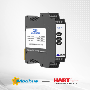







The MC0310 Modbus to HART built-in module is an embedded protocol conversion module developed by Microcyber for converting Modbus RTU slave devices to HART protocol slave devices.
The MC0310 is embedded in Modbus protocol input-type devices such as flow and level measurement instruments. It communicates with the Modbus device through a TTL-level interface, operates as a Modbus master and HART slave, and converts data from Modbus data registers into HART device variables and dynamic variables.
Modbus to HART Conversion
The MC0310 can convert a Modbus protocol flow meter or level meter into a corresponding HART protocol field device.
The module reads data from registers in the Modbus device, such as input registers and holding registers, and maps the data to HART device variables. These device variables can then be assigned to the four HART dynamic variables:
- Primary Variable (PV)
- Secondary Variable (SV)
- Tertiary Variable (TV)
- Quaternary Variable (QV)
For example, a holding register in a flow meter can store an instantaneous flow value. The register can be configured to a device variable of the MC0310, and that device variable can then be assigned to a HART dynamic variable.
The conversion logic can be represented as:
Modbus Data Register → HART Device Variable → HART Dynamic Variable
After configuration, a HART master can access the dynamic variables of the MC0310 through HART commands, allowing the data from Modbus registers to be transferred to the HART master.

Key Features of the MC0310
- Modbus RTU to HART protocol conversion
- Modbus master and HART slave operation
- TTL-level Modbus communication interface
- Support for configurable Modbus communication parameters
- Support for mapping Modbus data registers to HART device variables
- Support for 6 configurable device variables
- Support for HART PV, SV, TV and QV dynamic variables
- 4–20 mA analog current output for the primary variable
- Configuration through Microcyber configuration software
- Configuration through a HART master with DD file parsing capability
- Device status configuration
- PV range configuration
- Scaling factor configuration
- Batch configuration for multiple HART modules
4–20 mA Analog Current Output
The MC0310 provides a 4–20 mA analog current output corresponding to the HART primary variable (PV).
During normal operation, the module compares the primary variable with the configured upper and lower limits. When the primary variable is within the configured range, the analog current corresponds to the primary variable value.
The specified fixed output currents are:
| Condition | Output Current |
|---|---|
| Below the lower limit of the primary variable range | 3.800 mA |
| Above the upper limit of the primary variable range | 20.800 mA |
| Low current fault alarm | 3.70 mA |
| High current fault alarm | 21.750 mA |
The high and low fault alarm current can be configured through the configuration software.
When the HART polling address is set to a value other than 0, the analog channel outputs a fixed current of 4.000 mA. The analog current corresponding to the primary variable is available when the polling address is set to 0.
Modbus Communication
The MC0310 uses Modbus RTU for communication with the user’s Modbus device.
The module acts as the Modbus master, while the connected user device operates as the Modbus slave. The Modbus communication interface supports configurable communication parameters including slave address, baud rate, data bits, parity, stop bits and CRC byte order.
Modbus Communication Parameters
| Parameter | Default Value | Available Range / Option |
|---|---|---|
| Slave Address | 1 | 1–247 |
| Baud Rate | 9600 bps | 1200, 2400, 4800, 9600, 9200, 35700, 38400, 57600 |
| Data Bits | 8 | 7, 8 |
| Stop Bit | 1 | 1, 2 |
| Parity | EVEN | ODD, EVEN, NONE |
| CRC Byte Order | Low-High Order | Low-High Order, High-Low Order |
The MC0310 supports the following Modbus commands:
| Function Code | Function |
|---|---|
| 01 | Read Coil Status |
| 02 | Read Discrete Input State |
| 03 | Read Holding Register Value |
| 04 | Read Input Register Value |
| 05 | Write Coil |
| 16 | Write Multiple Register Values |
HART Communication
The MC0310 operates as a HART slave device.
The module supports HART common and general commands for device identification, process variables, dynamic variables, device status, polling address, primary variable range, analog output and device testing.
The module is shipped from the factory with a default HART polling address of 0.
Device Variable Configuration
The MC0310 supports the configuration of 6 device variables.
Device variables can represent data from the user’s Modbus device, including measurement variables such as:
- Flow
- Temperature
- Pressure
- Density
For each device variable, the configuration software provides settings for:
- Type
- Unit
- Sensor range upper limit
- Sensor range lower limit
- Minimum span
- Upper range value
- Lower range value
- Default unit
- Modbus function code
- Register address
- Register data type
The configured device variables can be assigned to the four HART dynamic variables, PV, SV, TV and QV.
Dynamic Variable Assignment
The MC0310 allows users to select up to four device variables from the six configured device variables and assign them to the HART dynamic variables.
The four dynamic variables defined in the HART protocol are:
PV → SV → TV → QV
The device variables can be mapped to these dynamic variables according to the user’s requirements.
One of the device variables can be assigned as the primary variable (PV). The PV is associated with the 4–20 mA analog current output in single-point mode.
MC0310 Configuration Software
The MC0310 can be configured using Microcyber’s host configuration software.
A HART master with DD file parsing capability, such as a PC or hand controller, can also import the DD file provided by Microcyber and perform the configuration.
The basic MC0310 configuration process consists of three steps:
1. Configure the Modbus Interface
Configure the Modbus interface according to the communication characteristics of the user’s Modbus device.
The configuration includes the slave address, baud rate, data bits, parity, stop bit and CRC byte order.
2. Configure Device Variables
Configure Modbus device data as the device variables of the MC0310.
The configuration includes the Modbus function code, register address, register data type, unit and range information.
3. Configure Dynamic Variables
Select device variables and assign them to the HART PV, SV, TV and QV dynamic variables.
After these three steps are completed, the operating mode can be changed to Operation Mode. The MC0310 then actively and cyclically sends Modbus requests to the user’s device to obtain the values of the configured device variables. The variables can be monitored in the configuration software.
Device Status Configuration
The MC0310 provides a device status configuration function.
The HART device status contains 8 states represented by 8 bits. In addition, the module can obtain status information from the user’s Modbus device and map this information to the HART additional device status.
The first three bytes of the additional device status are used by the HART module. The low 6 bits of the first byte indicate the read status of the six device variables, while the other two bytes represent 16 states of the user’s Modbus device.
The supplied DD file provides the additional device status bits in the form of Fld dev statB-b. If users need individual status names, the manual states that a dedicated DD file can be customized.
PV Range Configuration
The upper and lower limits of the primary variable range can be configured through the PV Range function.
The MC0310 supports configuration of the PV range source and the operating mode for the range values. The PV range source can be configured to use values set locally through the configuration software or values read from the user’s Modbus device.
When the PV range source is set to Remote, the upper and lower range values can be configured as Read Only or Read and Write.
Scaling Factor
The MC0310 provides a scaling factor for each device variable.
The conversion relationship is:
HART Device Variable = Modbus Device Variable × Scaling Factor
The factory default scaling factor is 1.0.
Commissioning and Calibration
The configuration software provides a commissioning and calibration area for checking the communication between the MC0310 and the user’s Modbus device.
After completing the hardware connection and configuring the Modbus communication parameters, users can use the Coil and Register functions in the calibration area to test the device.
If the returned and written data are correct, the hardware connection and Modbus communication parameters are considered correct according to the manual. If the result is incorrect, the hardware connection or software configuration should be checked.
Data Retention and Recovery
The MC0310 configuration software provides data saving and restoration functions.
The available operations include:
- Restore to factory default value
- Save to factory settings
- Restore to factory settings
Restoring to the factory default value returns all configuration data to the initial system values and causes the user-configured data to be lost.
Batch Configuration
The MC0310 provides a Batch Download function for configuring multiple HART modules.
After one MC0310 has been configured, its configuration information can be saved to a file. The saved file can then be opened when configuring other MC0310 modules, and the configuration data can be downloaded to the modules.
Hardware Interface
The MC0310 uses a 2.0 mm spacing interface for connection to the user’s board.
The hardware interface includes TTL-level UART communication signals, power connections, HART bus connections and communication status indication interfaces.
The relevant interface signals include:
| Pin | Name | Description |
|---|---|---|
| 3 | RESET | Reset signal, active low |
| 4 | GND | Reference ground |
| 6 | RXD | UART input, TTL level |
| 7 | TXD | UART output, TTL level |
| 13 | VCC-3.3V | Power output |
| 14 | VCC-5V | 5 V power output, customized |
| 27 | BUS+ | Bus power positive |
| 28 | BUS- | Bus power negative |
The manual specifies that the module uses a two-wire HART circuit with a TTL-level interface and no electrical isolation between the HART bus and the Modbus interface. The core module can be designed into 2-wire, 3-wire or 4-wire HART products.
Mechanical Dimensions
The MC0310 printed circuit board is 1.6 mm thick and rectangular in shape.
The manual specifies that the highest component on the front side is 5 mm above the board, while the highest component on the back side is 9 mm above the board. The remaining surface-mount components have a height of less than 4 mm.
Technical Specifications
| Parameter | Specification |
|---|---|
| Bus Power | 11.9–35 V |
| Bus Interface | 2-wire 4–20 mA + HART |
| Modbus Interface | TTL |
| Modbus Protocol | Modbus RTU Master Communication |
| Isolation | No isolation between HART bus and Modbus interface |
| Operating Temperature | -40°C to +85°C |
| Humidity Range | 5–95% RH |
| Storage Temperature | -40°C to +85°C |
| Start-up Time | ≤5 seconds |
| Update Time | 0.2 s |
| Damping Adjustment | 0–32 seconds |
| Alarm Signals | High and low alarm current: 21.75 mA / 3.7 mA |
| Upper/Lower Limit Current | 20.8 mA / 3.8 mA |
| Current Accuracy | 0.03% FS at room temperature |
| Current Temperature Drift | 50 ppm/°C |
| Intrinsically Safe Level | Ex ia IIC T4/T6 Ga |
The above values are taken from the MC0310 technical specification table in the user manual.
Troubleshooting
The MC0310 user manual provides the following troubleshooting information:
| Problem | Possible Reason | Recommended Action |
|---|---|---|
| Output current is 0 | Power failure or wire break | Repair the power supply or check the wire |
| Current is fixed at 21.75 mA or 3.70 mA | Communication failure between Modbus device and HART module | Check Modbus communication |
| Current is fixed at 4 mA | Meter is in multi-point mode | Change the slave address in standalone mode |
| Instrument cannot communicate | Connection failure or multi-point mode | Check circuit connection and network |
| HART communication light is not on | No HART communication or power supply failure | Check the HART host device, HART debugging demodulator, power supply and connection |
| Modbus communication light is not on | No Modbus communication or device failure | Check the Modbus device and connections |
| Modbus communication works but dynamic variable readings are incorrect | Incorrect device variable configuration or incorrect Modbus communication parameters | Check the data register address, data type, baud rate and parity |
MC0310 Model Selection
The MC0310 selection code is:
MOD-HART-M-N-T-M-N
| Code | Description | Option |
|---|---|---|
| M | Master-Slave | Master Station |
| N | Module Format | General |
| T | Hardware Interface | TTL Level |
| M | Software Interface | Modbus RTU |
| N | Bus Interface on Module | No Bus Interface |
Selection example:
MOD-HART-M-N-T-M-N
Frequently Asked Questions
What is the MC0310 Modbus to HART built-in module?
The MC0310 is an embedded module that converts Modbus protocol slave devices to HART protocol slave devices. It operates as a Modbus master and HART slave.
What Modbus protocol does the MC0310 use?
The MC0310 uses Modbus RTU for communication with the user’s Modbus device.
How many device variables can the MC0310 configure?
The MC0310 supports 6 device variables. These device variables can be assigned to the four HART dynamic variables PV, SV, TV and QV.
Does the MC0310 support 4–20 mA output?
Yes. The module provides a 4–20 mA analog current output corresponding to the HART primary variable.
What is the default HART polling address?
The default HART polling address is 0.
What is the Modbus interface of the MC0310?
The MC0310 uses a TTL-level Modbus interface.
Is the HART bus electrically isolated from the Modbus interface?
No. The manual states that there is no electrical isolation between the HART bus and the Modbus interface.
Can the MC0310 be configured with a HART hand controller?
Yes. A HART master with DD file parsing capability, such as a hand controller, can import the DD file provided by Microcyber and configure the HART module.
MC0310 Modbus to HART Built-in Module User Manual
For detailed configuration procedures, HART commands, Modbus communication settings, device variable configuration and troubleshooting information, refer to the MC0310 Modbus to HART Built-in Core Module User Manual.
Download the MC0310 User Manual
Contact Microcyber
For MC0310 Modbus to HART built-in module information, configuration requirements and product inquiries, please contact Microcyber Corporation.
Request a Quote