
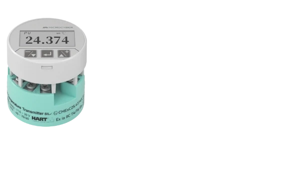
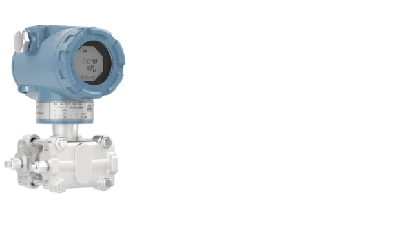
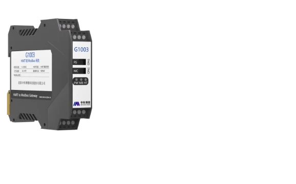
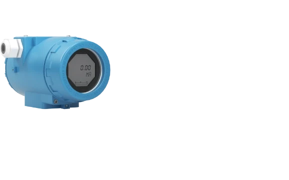


A temperature transmitter sits between a sensor and a controller. It takes the raw signal from an RTD or thermocouple and turns it into something a PLC or DCS can actually use, usually a 4-20 mA current, sometimes a digital signal riding on top of that current. Without it, the controller would need to interpret millivolt or resistance changes directly, which is neither practical nor accurate over long cable runs.
Where it sits in the loop
The typical arrangement is simple: sensor, transmitter, controller, final control element. The controller reads the transmitter output, decides what action is needed, and sends a command to a valve, heater, or cooling system. The transmitter’s only job is to make sure the number the controller receives actually reflects the process temperature, not sensor drift or cable resistance.

Two-wire and four-wire designs
Most industrial temperature transmitters are two-wire loop-powered devices. The same two wires carry the 4-20 mA signal and supply power to the transmitter electronics, which is why loop voltage and load resistance have to be checked against the transmitter’s supply range during design. A four-wire transmitter separates these functions: two wires for power (AC or DC depending on the model) and two dedicated signal wires to the controller. Four-wire designs give more flexibility on power source but add wiring cost, so they show up more often in panel-mounted or multi-channel applications than in field-mounted single-loop instruments.
RTD or thermocouple, and why some transmitters take both
An RTD changes resistance with temperature. A thermocouple generates a small voltage from the junction of two dissimilar metals. Thermocouples always have two leads; RTDs can be wired with two, three, or four leads, with three- and four-wire configurations used to cancel out lead resistance error over longer cable runs. Because the input electronics for these two sensor types are different, a transmitter that accepts both needs configurable input stages. Many general-purpose transmitters on the market today support Cu50, Cu100, Pt100, Pt1000 and similar RTD curves alongside B, E, J, K, N, R, S, T thermocouple types in one unit, so the same hardware can be configured for whichever sensor is already installed.
From analog to digital: HART, FOUNDATION Fieldbus, PROFIBUS
A “smart” transmitter still outputs 4-20 mA (or a fieldbus signal), but it also carries diagnostic and configuration data: tag name, range, sensor type, and status flags such as NE107-style condition indicators on newer designs. Three output protocols dominate the process industry, and the choice usually comes down to what the rest of the plant already runs.
| Output type | What rides on the signal | Typical use case |
|---|---|---|
| 4-20 mA + HART | Analog current plus digital HART frames | Point-to-point loops, retrofits into existing 4-20 mA systems |
| FOUNDATION Fieldbus H1 | Fully digital, multi-drop bus | New builds standardizing on FF for control-in-the-field |
| PROFIBUS PA | Fully digital, multi-drop bus, intrinsically safe segments | Plants standardized on Siemens/PROFIBUS DCS architecture |
As a concrete reference point, a single-channel HART transmitter such as the NCS-TT106H runs on 12-42 VDC (non-IS) or 12-30 VDC (IS), holds 0.03% current accuracy, and responds within 0.5 s. The FF and PROFIBUS PA variants of the same platform (NCS-TT106F, NCS-TT106P) drop to a 9-32 VDC bus supply with quiescent current under 14 mA, since fieldbus segments have their own current budget per spur. None of these numbers are universal across brands, so they’re worth checking on the actual datasheet rather than assumed from the protocol name alone.
Calibration: what zero and span actually mean
Calibration lines up the transmitter’s output range with the process temperature range it’s meant to measure. If the loop is scaled for 0-100°C, the transmitter needs to output 4 mA at 0°C and 20 mA at 100°C, with everything in between tracking linearly (or per the sensor’s characteristic curve, which the transmitter linearizes internally).
Older transmitters did this with physical zero and span potentiometers. A calibrator injects a simulated resistance or millivolt signal at the lower range value, and a technician trims the zero pot until the output reads 4 mA. The same is repeated at the upper range value using the span pot for 20 mA. Because zero and span interact somewhat on older analog designs, this is usually an iterative adjustment rather than a single pass.
Newer transmitters skip the potentiometers entirely. Range and linearization are set through a HART communicator, a DTM/FDT configuration tool, or a USB/serial connection to a laptop, and the values are stored digitally. This removes drift from mechanical trim pots but shifts the requirement toward keeping calibration software and device description files up to date.

Wireless transmitters: not just “no wires”
Wireless transmitters remove the signal cable, but the protocol underneath matters more than the fact that it’s wireless. Industrial deployments typically use WirelessHART rather than a generic Wi-Fi link, because WirelessHART is a mesh network standard built for process environments, with each device able to relay data for its neighbors. A battery-powered WirelessHART transmitter such as the NCS-TT105W operates in the 2400-2500 MHz band with a transmission range around 150 m and draws from a 19000 mAh, 3.6 V battery pack, sized against the configured update rate rather than a fixed runtime figure. Where a wireless signal needs to reach an existing 4-20 mA loop, a gateway converts WirelessHART traffic back to a wired protocol, rather than the transmitter broadcasting a raw analog value over the air.

Choosing between them
For an engineer specifying a transmitter, the practical checklist usually comes down to: single or dual channel, output protocol matching the host system, response time versus damping needs for the loop, isolation voltage if the sensor and control system share a ground reference risk, and explosion protection rating if the installation is in a hazardous area. These aren’t interchangeable trade-offs; a dual-channel transmitter with a faster response time typically costs more and may need a different mounting footprint than a single-channel field unit.
Microcyber’s NCS-TT106 series covers this range of outputs on one hardware platform: 4-20 mA/HART, PROFIBUS PA, FOUNDATION Fieldbus H1, PROFINET RT, and Modbus RTU variants share the same RTD/thermocouple input handling, while the NCS-TT105 series adds dual-channel input and flameproof (Ex d) housing options for harsher installations. The full parameter tables, including response time and explosion-protection codes by variant, are in the datasheet: NCS TT106H Intelligent HART Temperature Transmitter User Manual.
Questions on wiring a specific loop or picking between HART and PROFIBUS PA for a retrofit can go to .