


Modbus to HART Gateway G0310: Protocol Conversion for Legacy Modbus Instruments
In brownfield industrial automation projects, integrating legacy Modbus RTU devices with modern HART-based DCS, SCADA, or asset management systems presents significant challenges. The G0310 بوابة Modbus إلى HART from Microcyber enables seamless protocol conversion, allowing existing RS485 Modbus instruments to output multivariable data and diagnostics over HART protocol while preserving the conventional 4-20mA analog signal.
Protocol Conversion Architecture and Supported Standards
The G0310 functions as a Modbus RTU Master on the RS485 interface, polling field devices with standard function codes (01, 02, 03, 04, 05, 06, 16). On the HART side, it operates as a HART 7-compliant slave, mapping up to six Modbus registers to HART device variables (0–5) and assigning them to dynamic variables (PV, SV, TV, QV). This dual-output capability (4-20mA analog + superimposed HART digital) ensures compatibility with both legacy analog I/O and modern digital systems.
Physical and Environmental Specifications
Designed for industrial reliability, the gateway features 12–42 VDC power supply, 500 VAC isolation between Modbus and HART interfaces, operating temperature range of -40°C to +85°C, and IP20 protection. It supports DIN-rail mounting with compact dimensions (99 × 22.5 × 114.5 mm) and weighs approximately 0.2 kg, making it suitable for control cabinets in harsh environments.

Installation and Wiring Guidelines for Reliable Operation
HART Loop Requirements and Resistance Management
HART communication requires a total loop resistance of 230–1100 Ω (commonly 250 Ω minimum for reliable FSK signaling). Add a 250 Ω series resistor if loop resistance is insufficient. For optimal performance, use shielded twisted-pair cable for RS485 (A+ to A+, B- to B-) and maintain separation from interference sources such as variable frequency drives.
Supported Topologies: Point-to-Point and Multi-Drop
In point-to-point mode (HART address 0), the gateway supports combined analog and digital communication for direct integration with analog input modules or handheld communicators. Multi-drop mode (addresses 1–15) enables pure digital HART communication, connecting multiple gateways on a single loop to reduce wiring in distributed installations.
Configuration and Data Mapping Best Practices
Modbus Register to HART Variable Mapping
Map Modbus holding/input registers (supporting 16-bit/32-bit integers or floating-point) to HART device variables, ensuring byte order matches the source device (low-byte-first default). Verify mappings by reading known values with a Modbus master tool, then confirming HART output using a communicator such as Emerson 475 or Trex to prevent data corruption from endianness mismatches.
Damping and Signal Conditioning Settings
Adjust damping time constant (0–32 seconds) according to process characteristics: 0.2–1 second for dynamic variables like flow, and 2–5 seconds for slower processes like level to reduce noise while maintaining responsiveness. Refresh time is typically 0.2 seconds, with startup under 5 seconds.
Industrial Application Examples and Benefits
Petrochemical and Refinery Retrofits
In aging tank farms, Modbus-based radar level gauges and flow meters are converted to HART without hardware replacement, enabling multivariable data access in HART DCS systems during maintenance windows and avoiding costly shutdowns or full instrument swaps.
Water/Wastewater and Power Generation Monitoring
Electromagnetic flow meters transmit instantaneous flow, totalizer, conductivity, and temperature over a single loop in wastewater plants. In power plants, auxiliary vibration and temperature sensors feed HART-compatible SIS for predictive maintenance and plant-wide data integration.

Deployment Considerations and Model Selection
Conversion Direction and Power Requirements
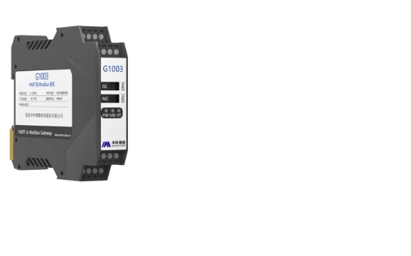
The G0310 is specifically Modbus Master to HART Slave. For HART to Modbus conversion, refer to alternative models such as G1003. External 12–42 VDC power is required for the Modbus side; the HART interface is loop-powered. Verify polarity and jumper settings (failure warning current and configuration protection) during installation.
Compliance and Long-Term Reliability
Compliant with relevant EMC standards (GB/T 18268 series) and supporting wide environmental tolerance, the gateway ensures stable performance in demanding process industries. Periodic checks of loop resistance, mapping accuracy, and communication parameters maintain optimal system reliability.
(FAQ)
What is the main purpose of the G0310 gateway?
The G0310 converts Modbus RTU signals from legacy field instruments into HART protocol, enabling multivariable data (PV, SV, TV, QV) and diagnostics to be transmitted over existing 4-20mA loops to modern HART-compatible control systems without replacing the instruments.
Can the G0310 be used in multi-drop HART networks?
Yes. In multi-drop mode (HART addresses 1–15), multiple G0310 gateways can be connected on the same HART bus for pure digital communication, significantly reducing wiring requirements in distributed field applications.
What should I do if HART communication is unstable?
First, verify loop resistance is within 230–1100 Ω (add a 250 Ω resistor if needed). Check cable quality, shielding, grounding, and distance from interference sources. Also confirm correct baud rate, parity, and address settings on both Modbus and HART sides.
Does the gateway support floating-point data from Modbus devices?
Yes. It supports 32-bit floating-point mapping. Ensure the byte order (endianness) matches the source instrument. Always validate the mapping using a Modbus polling tool and a HART communicator before commissioning.
Is the G0310 suitable for hazardous area installation?
The standard G0310 is rated IP20 and designed for installation inside control cabinets or junction boxes. For hazardous (Ex) areas, consult the manufacturer for certified versions or use appropriate enclosure and intrinsic safety barriers.
How is the G0310 configured?
Configuration is performed via a dedicated serial configuration tool (USB/RS232 connection). Parameters include Modbus polling settings, register-to-variable mapping, HART address, damping time, and failure mode behavior. No web interface is available.